Top Wiring Mistakes in an Automation System
(and How We Avoid Them)
In automation and industrial machinery, downtime is one of the most costly obstacles you can encounter. Whether it’s a single cell in a production line or a full system shutdown, the impact of halted production, idle staff, and missed deadlines adds up quickly.
But downtime isn’t just a problem once the machine is operational—it can be just as disruptive during the build and commissioning phases, causing delays for both the machine builder and the end client. Early-stage downtime not only affects delivery schedules but can also strain project budgets and damage customer confidence.
And in our experience, a surprising amount of downtime can be traced back to one root cause: bad wiring.
From unlabeled wires, low quality connections to poor grounding practices, these aren’t just “neatness” issues. They’re performance issues. They impact reliability, safety, and the long-term serviceability of your machines.
Here are four of the most common wiring mistakes we see in the field and exactly how we prevent them in every job we take on.
1. Poor Labeling
Wire and device labeling might seem like a small detail—until you’re standing in front of a panel with dozens (or hundreds) of unmarked wires and a machine that won’t start.
The Problem:
When wires and devices aren’t clearly labeled, technicians waste time trying to trace connections back through terminals, ducting, and enclosures, and issues locating specific devices that are not labelled is time consuming when the chips are down.
Mislabeling or inconsistent labeling across a project makes it even worse. That time- consuming process can grind troubleshooting and commissioning to a halt.
In the heat of production deadlines, this is more than an inconvenience—it’s a liability.
Our Approach:
At Electrilogix, we ensure every single wire and device is labeled using durable, legible markers. Labels are printed, not handwritten, and aligned to match the project’s schematics and layouts exactly. All labels are facing the same directions (tilt head to left method), and all labels are installed to be visible without having to take things apart when possible.
We follow structured labelling conventions that make sense to whoever’s opening that panel—whether it’s tomorrow or five years from now.
When a client standard is required for labelling, we ensure that it is followed, without compromise.
Clear labeling isn’t just for us—it’s a gift to the next electrician, or the technician doing maintenance and debugging. This saves hours in commissioning and years of frustration down the road.
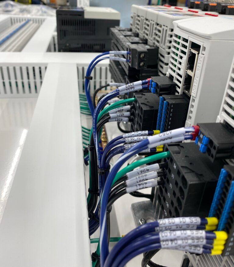
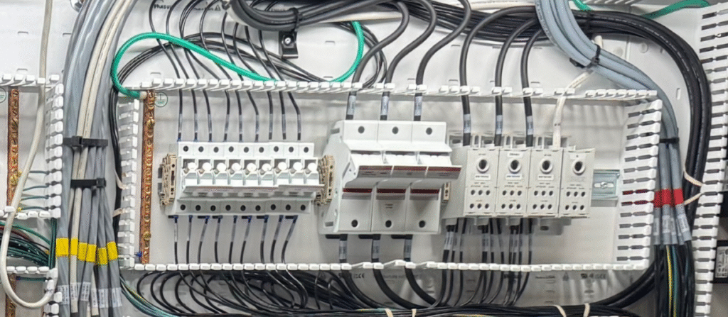
Wire labeling shown, all facing the same direction, clear and concise, and spaced evenly from connector.
Device labels on every component and terminal for easy identification during troubleshooting.
2. Poor Connections and Crimping Techniques
Even perfectly routed and labeled wiring can cause major issues if the terminations aren't reliable. This is one of the most common—and dangerous—oversights we find when inspecting failing panels or erratic machines.
The Problem:
Loose or improperly crimped connectors can cause:
- Intermittent or definitive faults
- Communication and noise issues
- Excessive heat buildup
- Arcing and tracking
- Premature failure of components
- Fire hazards in worst-case scenarios
- Intermittent or definitive faults
- Communication and noise issues
- Excessive heat buildup
- Arcing and tracking
- Premature failure of components
- Fire hazards in worst-case scenarios
These problems often don’t appear right away. They tend to surface weeks or even months later—typically when the system is under peak load or running continuously. To make matters worse, they can be extremely difficult to diagnose, often leaving maintenance electricians stumped and leading to extended periods of costly downtime.
Our Approach:
We treat every connection as a critical point of failure prevention.
We use:
- High-quality ferrules, connectors and terminals and NEVER more conductors
than permitted in any given connector or terminal - Precision ratcheting crimping tools that we inspect frequently
- The correct screwdriver/hand tool for the correct terminal
- Industry-standard torque practices that are documented as required
- Special attention made to ensure that finger safe integrity is maintained where required on every connection by ensuring that conductive parts of our connections are not exposed
- Analysis of every terminal type prior to wiring to ensure that proper connection is maintained and that over or under insertion does not result in “missed” connections, or connections made on insulated parts of the connectors
- Inspection and tightness check after every crimp and connection for consistency and integrity
Our team is trained to work to a strict internal standard: no loose strands, no over/under-crimping, no shortcuts, and no moving on until every connection is double checked.
The goal is simple: no surprises, no weak links.
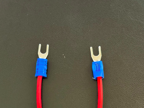
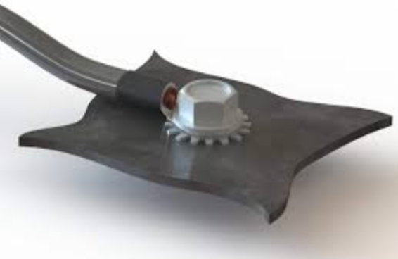
Connector on the left is properly crimped using a ratcheting style crimper and NEVER a “pliers” style as shown on the right. We’ve tested the difference, and it is not even close.
3. Improper Grounding and Shielding
As automation systems become more complex, with noise sensitive I/O and devices, high-speed communication, and power electronics like VFDs and Servo drives, grounding/bonding and shielding have become mission-critical. Unfortunately, they’re still frequently misunderstood or ignored altogether.
The Problem:
Improper grounding can lead to:
- Equipment malfunctions
- Sensor inaccuracies or “ghost readings”
- Unexplained signal drops or network communication errors
- VFD / Servo-induced electrical noise
- Ground loops, which are difficult to detect and fix
- Equipment malfunctions
- Sensor inaccuracies or “ghost readings”
- Unexplained signal drops or network communication errors
- VFD / Servo-induced electrical noise
- Ground loops, which are difficult to detect and fix
Many of these issues can seem like phantom problems; difficult to diagnose and even harder to pinpoint. The best way to prevent them is by thoroughly understanding both the electrical code and the manufacturer’s grounding and bonding requirements during the build phase—and ensuring those requirements are properly implemented.
Our Approach:
We implement a structured, code-compliant grounding scheme on every project. This includes:
- Bonding every metal enclosure, backplate, wireway, duct, door and metal non current carrying component to ground, as required by code, manufacturers requirements, and industry best practice
- Understanding and implementing sound grounding and bonding techniques such as the thorough removal of paint when required, the use of star washers to ensure continuity through painted surfaces, and ensuring all bonding connections are sound and tight
- Proper grounding and bonding techniques of main services and separately derived systems
- Terminating shielded cables at one end only (typically at the source), unless specified otherwise
- Ensuring VFD and Servo system grounding is properly done per manufacturers requirements (It is highly common to find this done incorrectly)
- Physically separating signal and power wiring where possible to minimize crosstalk
- Complying with Ontario Electrical Safety Code (OESC) and CSA C22.2 grounding standards
Good grounding and bonding doesn’t just protect your investment—it keeps your system running smoothly and predictably.
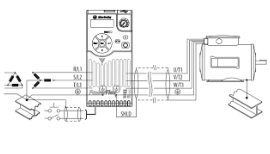
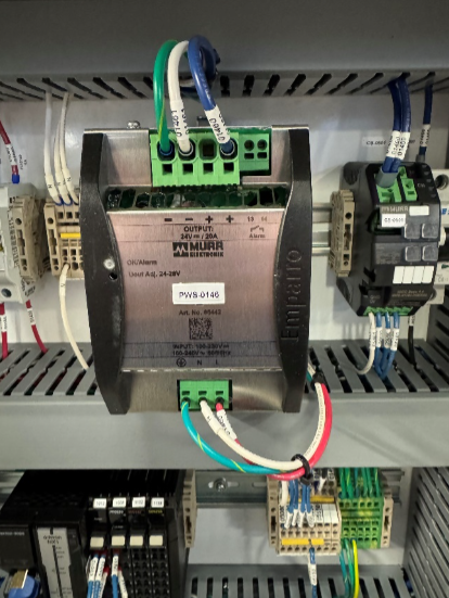
VFD grounding/bonding the RIGHT way. Motor case ground should go uninterrupted directly back to the VFD, and never through terminals or bonding strips.
The use of star washers is required when paint removal is impractical in order to “bite” through paint to ensure bonding integrity.
4. Ignoring the Needs of the ‘Next Electrician’
One of the most frequently overlooked aspects of panel building and machine wiring is planning for the electricians and technicians who will interact with the system throughout its lifecycle. This includes floor electricians who are responsible for terminating field wiring during the later stages of the build, often under tight time constraints, as well as maintenance personnel who may be tasked with troubleshooting, servicing, or modifying the system months—or even years—after installation. Planning panel builds and field wiring with these future users in mind ensures the system remains understandable, maintainable, and safe well beyond initial commissioning.
This consideration becomes even more important when the machine is torn down for shipping and reinstalled at the customer’s site. Clear labeling, accessible terminal blocks, and thoughtful routing make it much easier to disconnect, transport, and reassemble the system without confusion, errors, or delays during commissioning.
At Electrilogix, we call this "internal customer thinking"—because if we don’t plan for it, someone else pays the price in time, frustration, and cost.
The Problem:
Many control panels and machines are wired in ways that block access to terminal blocks, overload wireways, or ignore how field wiring will be routed. This makes tying in cables difficult, slows commissioning, and frustrates anyone trying to troubleshoot later.
Our Approach:
We wire with floor electricians and service techs in mind. That means:
- Keeping terminal strips accessible and planning for a “panel” side and “field” side to terminal blocks to keep tie ins seamless and isolating circuits simple.
- Routing internal panel wiring in a way that plans for the field tie in to ensure ducts will be evenly filled once tie ins and install is completed
- Planning the layout around the expected direction of incoming field cables and marking the landing point of field cables to ensure repeatable wiring when the machine is torn down and reinstalled at site
- Planning and executing field wiring in a way that will allow for future access for maintenance
- Maintaining service loops where needed and labeling everything clearly
This planning ensures that field cable tie-ins are logical, efficient, and frustration-free and that field cables are easy to locate and maintain. It also reduces risk of installation
errors and cuts down on commissioning delays.
“Internal Customer Thinking” – Field cable landing areas left unobstructed by internal panel wiring when possible and coloured tape applied to field cables to ensure repeatable landing spots during tear down and final install.
The Electrilogix Standard
We’ve built our name on wiring that performs under pressure—and holds up over time. With 30+ years in the industrial and automation space, we know what works and what causes problems.
Every job we take on reflects:
- Clear labeling
- Solid terminations
- Standards-compliant grounding
- Access for maintenance and field integration